|
NUMERICAL ANALYSIS
OF OPTICAL AND ELECTROMAGNETIC PHENOMENA LINEAR POLARIZED
LIGHT MALUS’ LAW Ian
Cooper matlabvisulaphysics@gmail.com Matlab
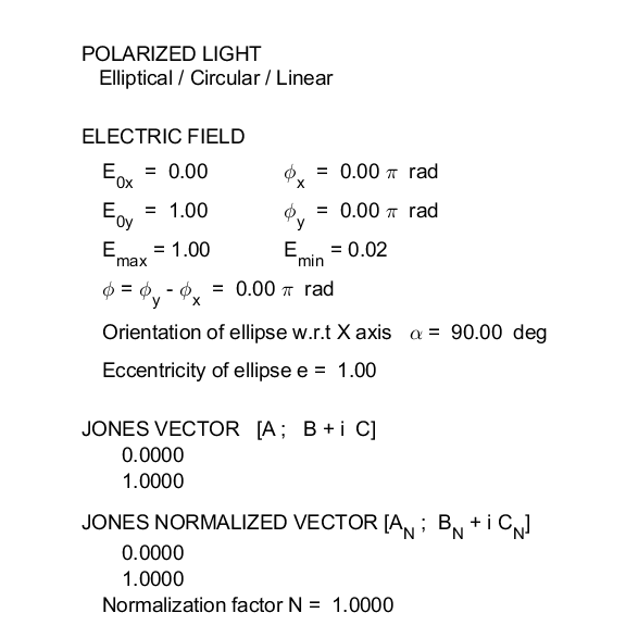
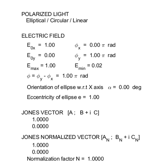
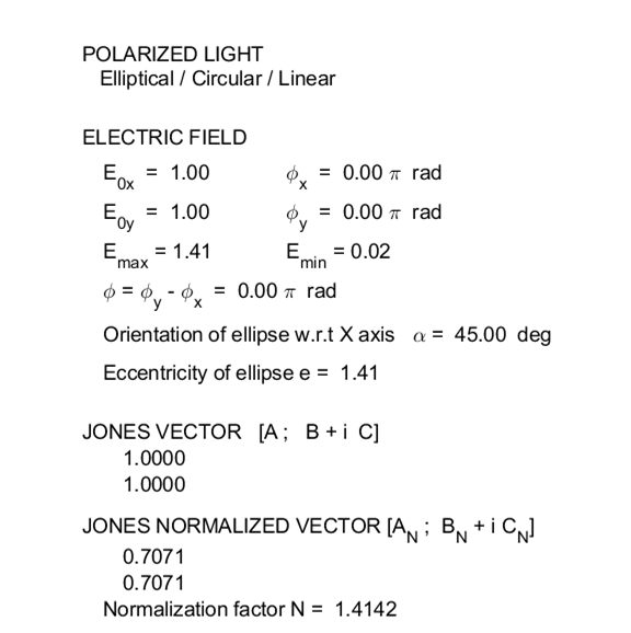
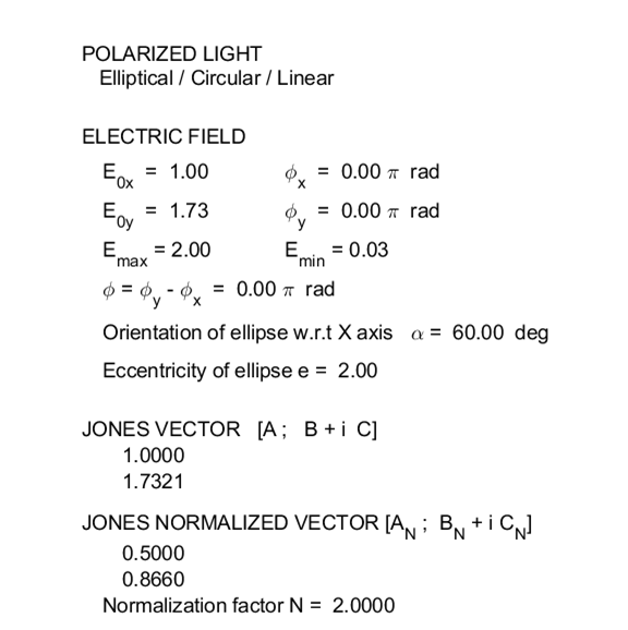
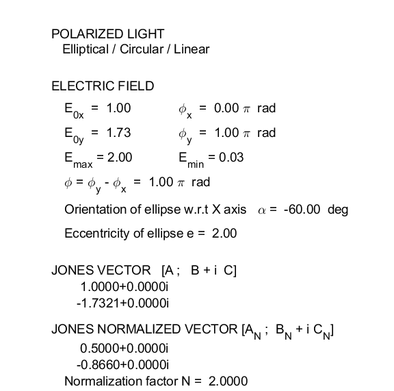
Script Download Directory op_005.m The Script op_005.m can be used
to model the any type of polarization. The animations of the electric field
vector can be saved as animated gif files (flag1 and flag2). In
the INPUT SECTION of the Script, you can enter the amplitudes of the electric
field components and their phase angles (flagP = 1) or
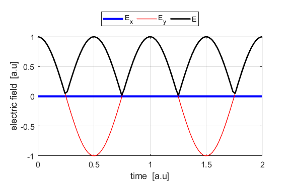
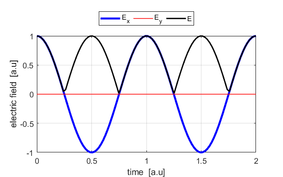
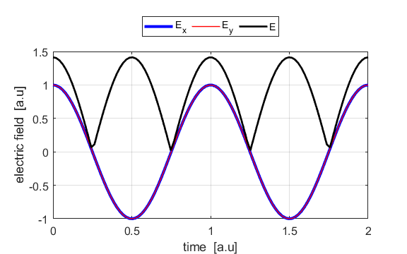
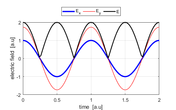
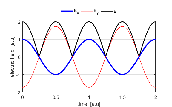
the Jones parameters (flag2 = 2). From the input values, the electric field (E,
Ex, Ey) as functions of time t and position z are
calculated. In any plane (z = constant), the electric field vector sweeps out
an ellipse with time (a straight line: linear polarization and a circle:
circular polarization are special cases of an
ellipse). The time evolution of the magnitude of the electric field is used
to find its maximum Emax and minimum Emin values and the angle op_006.m The Script is used to give an animation which illustrates
Malus’ Law. Unpolarized light is passed through a polarizer to produce
linear polarized light. The light then passes through an analyzer
that rotates through an angle
Background document: Mathematical foundations Visual Physics Online: Polarization 1. Vertical Polarized Light
2. Horizontal Polarized Light
3. Linearly Polarized Light
4. Linear Polarized Light
5. Linearly Polarized Light
POLARIZATION BY
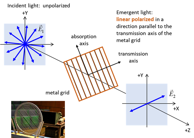
SELECTIVE ABSORPTRION AND MALUS’ LAW The absorption of light strongly along one direction and easily transmitted along a perpendicular direction is best understood by considering an experiment with microwaves as shown in figure 1.
Fig. 1. Action of a metal grid on an
unpolarized microwave beam. All components of the electric field parallel to
the metal grid are absorbed and all components perpendicular to the metal
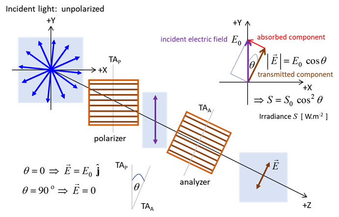
grid are transmitted provided Provided that the wavelength Consider unpolarized microwave radiation incident upon a metal grid aligned in the horizontal direction (assume the polarizer is ideal). Then, only the vertical components are transmitted whereas the horizontal components absorbed. This vertical direction is called the transmission axis (TA) of the polarizer. A second polarizer known as the analyzer whose transmission axis can be rotated can be used to test the state of polarization. When the TA of the anlayzer is oriented at 90o relative to the polarizer, the light is effectively extinguished. As the angle is reduced from 90o to 0o, the light transmitted through both the polarizer and analyser increases, reaching a maximum at 0o where the two transmission axes are aligned.
Fig. 2. Malus’ Law. Action of a horizontal metal grid polarizer and a rotatable analyzer on microwaves. For the arrangement of the optical elements as shown in figure 2, the transmitted electric field amplitude is
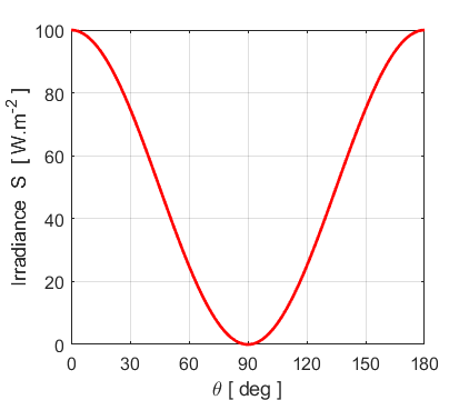
and the irradiance S is proportional to the square of the amplitude, hence
which is a statement of Malus’ law. Malus’ law applies to all forms of electromagnetic radiation. For visible light, a dichroic polarizer selectively absorbs light with electric field oscillations along a unique direction characteristic of the dichroic material. The dichroic polarizer easily transmits light with electric field oscillations along a direction orthogonal to the direction of absorption. Dichroism means that light propagating in a given direction will be absorbed differently depending on the orientation of the electric field. A naturally occurring material that can act as a dichroic polarizer is the mineral tourmaline. The most common dichroic polarizer is a material called polaroid invented in 1938 by E.H. Land. When a clear sheet of polyvinyl alcohol is heated and stretched, its long hydrocarbon molecules tend to align in the direction of stretching. The stretched sheet is them impregnated with iodine atoms which become associated with linear molecules and provide free (conduction) electrons which act as the free electrons in the metal grid. For dichroic materials, complete cancellation of the forward propagating wave does not occur and most of the energy is dissipated (absorbed) rather than the cancellation due to the interference of the incident wave and the generated wave. We can use a Matlab Script (op_006.m) to model red light passing through a
polarizer and analyser as the analyser is rotated through an angle
Fig. 3. Crossed polarizers and Malus’ law (figure 2): When the TA axes are parallel, maximum light is transmitted through optical elements. When the two TA axes are perpendicular to each other, minimum light is transmitted. |