open_echo
Open Echo TUSS4470 Shield Getting Started Guide
The TUSS4470 is an ultrasonic driver and receiver IC designed for seamless interaction with ultrasonic transducers. The TUSS4470 Arduino Shield is a development board that enables quick evaluation of the TUSS4470’s features using the Arduino UNO platform.
Overview
This repository provides a quick-start guide and example Arduino sketches for experimenting with Time-of-Flight (ToF) applications using the TUSS4470. The shield is ideal for development, testing, and prototyping, but is not intended as a finished consumer product.
Getting Started
Connect the shield to an Arduino UNO.
Upload one of the provided example sketches to explore different features of the TUSS4470.
Use the Python software to see the echoes.
Ordering
The shield can be easily ordered via JLCPCB or other PCB fabrication services.
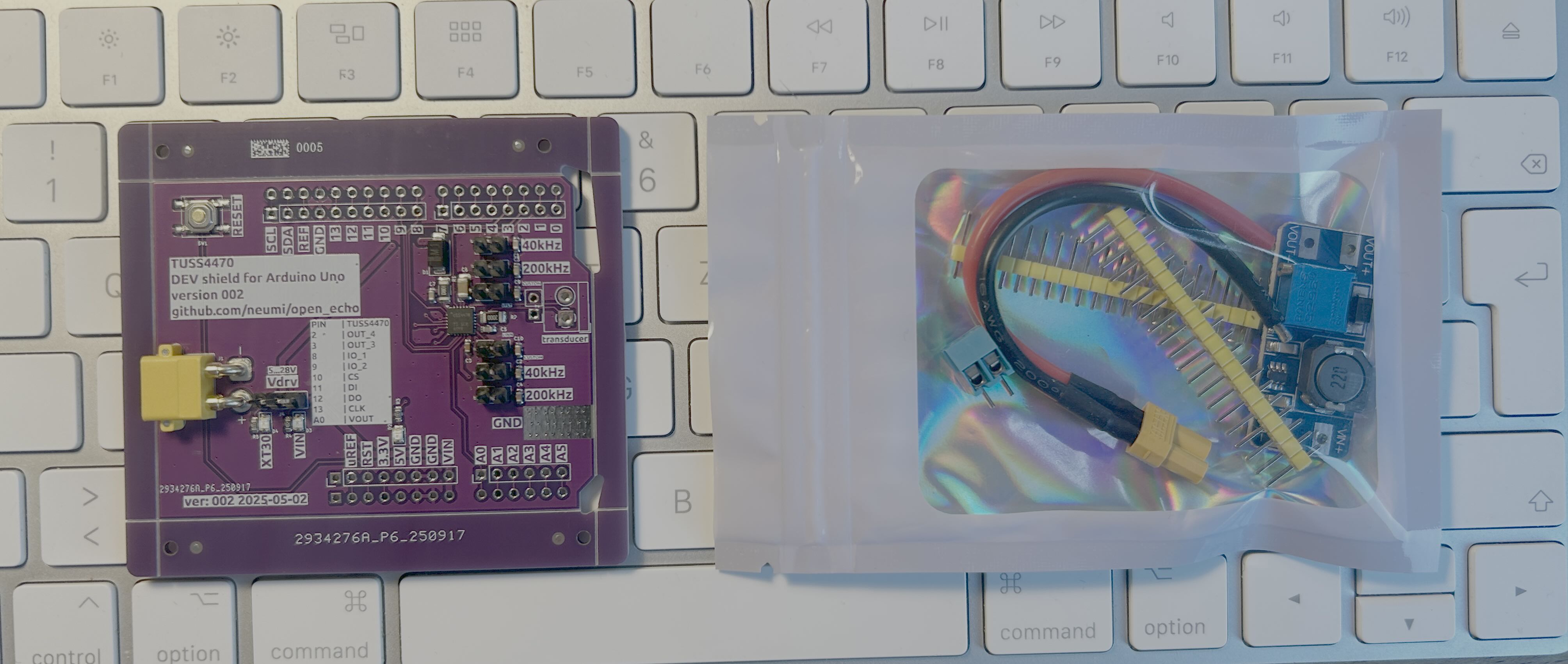
[!Note] I just got a few new boards, I sell as starter kits. Feel free to DM me on Discord if you’re interested. Or send an email to: openechoes@gmail.com One assmebled board is 50€ + shipping. (10/2025)
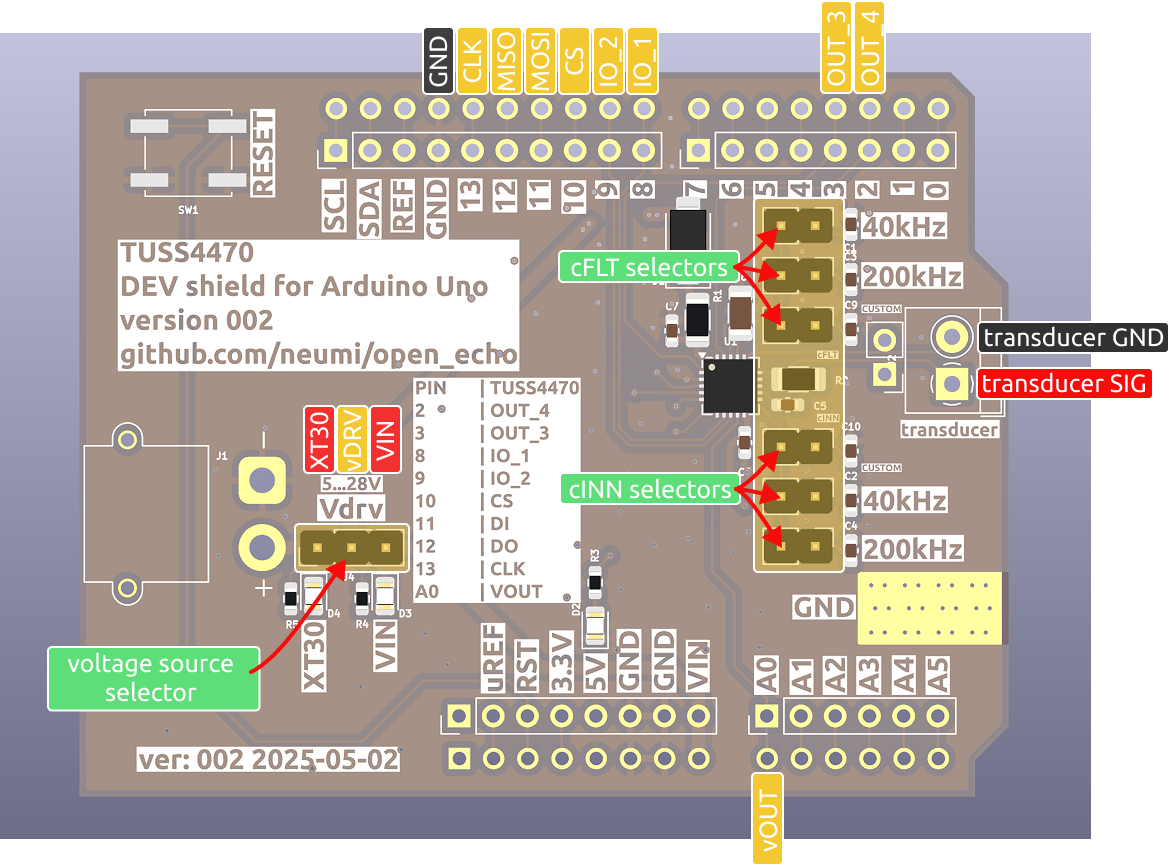
Electrical Connections
The TUSS4470 Shield is designed specifically for use with the Arduino UNO. It is not software- or pin-compatible with other Arduino boards at this time.
Pin Connections
The shield interfaces with the Arduino UNO the following:
- SPI interface
- Four digital GPIOs
- Analog pin A0
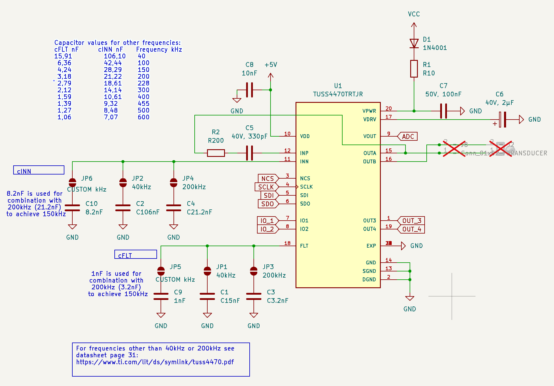
cINN and cFLT Filtering Capacitor Selection for Transducer Frequency
To support different ultrasonic transducers and their respective drive frequencies, the board provides preset capacitor options for 40, 150, 200 (and 600) kHz</b>.
[!Important] Use the onboard jumpers to select the appropriate cINN and cFLT values.
Custom Capacitor Configuration
If you need to drive transducers at frequencies other than the provided presets and combinations (40 kHz, 150 kHz, 200 (and 600) kHz), you can customize the capacitor values:
- Desolder the default “CUSTOM” capacitors. (for cINN and cFLT)
- Solder your own calculated capacitor values onto the “CUSTOM” pads.
[!TIP] Capacitors can be combined in parallel to achieve intermediate values. For example, to support 150 kHz, both the 200 kHz and CUSTOM capacitors are used in parallel to produce the required total capacitance. On board version 002, “Custom” is pre-selected to match the right capacitances together</b> with the 200kHz capacitors for 150kHz.
Below is the electrical connection layout for the cINN and cFLT capacitors and jumpers:
Power Supply Options
The board supports two power input options:
-
VIN (Arduino VIN pin): Use this when the transducer operates at 12V max, as the Arduino cannot tolerate higher voltages.
-
XT30 Connector: Use this if you require higher voltage (up to 28V max) for more powerful transducers.
-
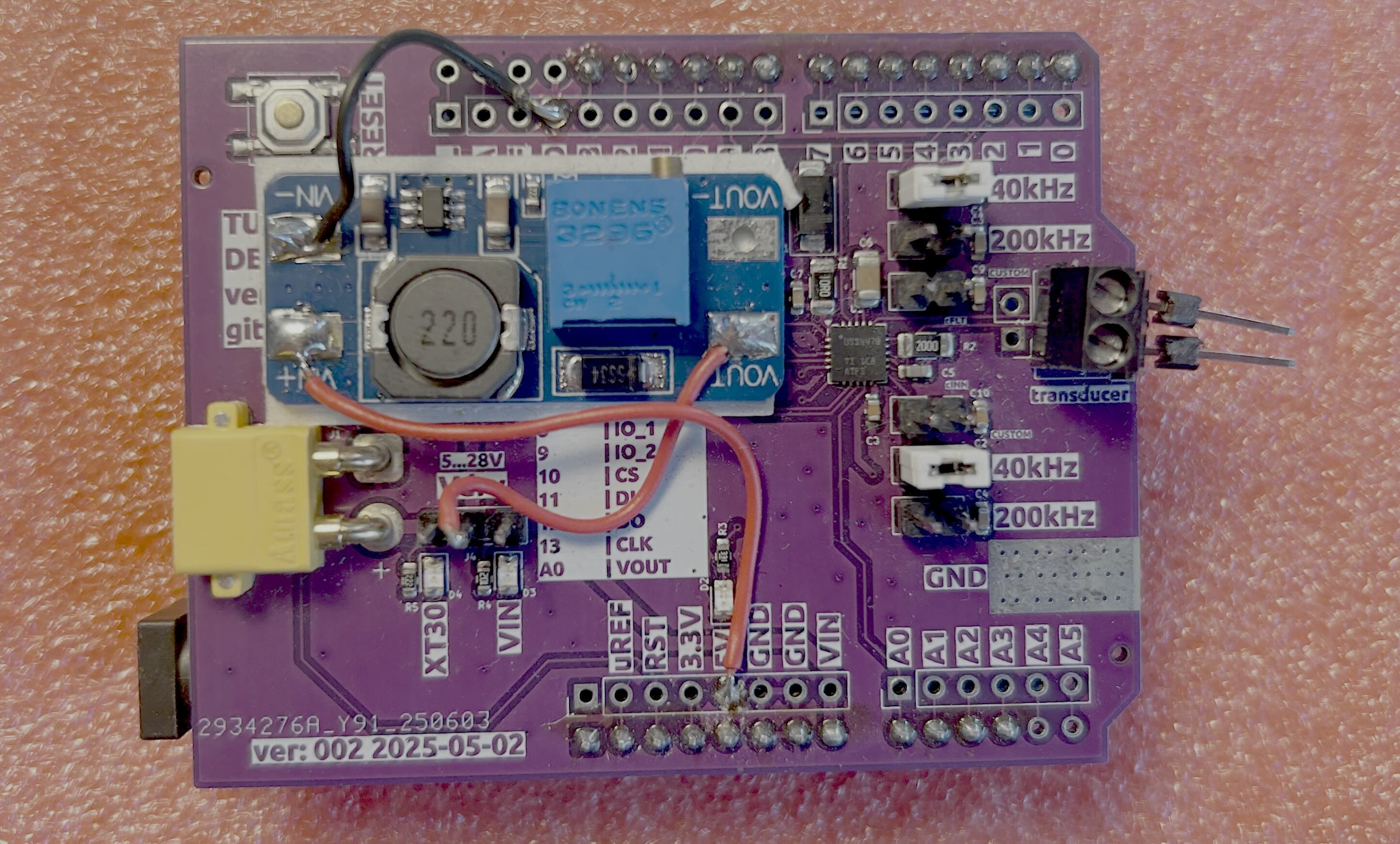
MT3608 Boost Converter: You can add an MT3608 boost converter to your board to generate a higher vDRV from the USB 5V supply. This solution is reliable and works well in many applications, such as powering marine transducers. Simply take the MT3608 module (included in the starter kits), secure it to the shield with double-sided tape, and connect the three wires as shown:
[!Tip] To get started, use a 12V power supply. Many ultrasonic transducers operate reliably at this voltage.
Lower voltages may not adequately excite the transducer, resulting in weak or no echo signals.
The MT3608 should not be turned much further than 22V, as it becomes unstable.
[!Warning] Do not exceed 28V input. Higher voltages can damage the board or components. Ensure proper polarity!
Transducer Connection
Connect your PZT crystal or preassembled ultrasonic transducer to the “Transducer” header:
- Top pin: Ground (GND) / Shield
- Bottom pin: Signal
[!Important] Proper polarity is crucial to minimize electrical noise and ensure optimal performance. For transducer connections exceeding 10 cm in length, use coaxial cable. Connect the cable shield to the transducer ground (GND).
The recommended setup is illustrated below:

[!Important] Always connect GND/Shield to the TOP pin on the transducer. Using the wrong pin increases powerline noise and significantly weakens the signal.
Below: Comparison of a transducer wired incorrectly (left half) vs. correctly (right half).

Next Steps: Proceed to Getting Started with Arduino TUSS4470 Firmware.</b>