3.2. The Blueprints Input File
The blueprints input defines the dimensions of structures in the reactor, as well as their material makeup. In a typical case, pin dimensions, isotopic composition, control definitions, coolant type, etc. are defined here. The specifics of each assembly type are then overlayed, possibly including enrichment distributions and other material modifications.
Note
See the blueprints module for implementation and more detail.
This input file is formatted using YAML, which allows text-based change tracking for design control. ARMI does not have a blueprints-editing GUI yet, but may in the future.
Note
You can point many ARMI runs to the same Blueprints input file using full paths in loadingFile setting.
ARMI models are built hierarchically, first by defining components, and then by larger and larger collections of the levels of the reactor.
3.2.1. Blueprint sections
The blueprints input file has several sections that corresponds to different levels of the reactor hierarchy. You will generally build inputs “bottoms up”, first by defining elementary pieces (like pins) and then collecting them into the core and reactor.
The ARMI data model is represented schematically below, and the blueprints are defined accordingly:
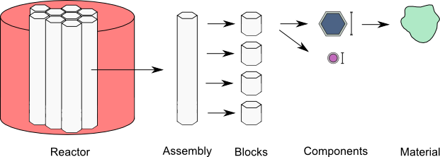
Figure 1. The primary data containers in ARMI
- blocks:
- asssemblies:
Defines vertical stacks of blocks used to define the axial profile of an
Assembly.- systems:
Reactor-level structures like the core, the spent fuel pool, pumps, the head, etc.
- nuclide flags:
Special setting: Specifies nuclide modeling options, whether a nuclide is being modeled for cross sections and/or depletion. For instance, it allows you to ignore nuclides above Curium for depletion speed.
- custom isotopics:
Special setting: defines user-specified isotopic compositions.
Warning
YAML is not order specific; however, one of the techniques used to limit the size of the input
includes using YAML anchors to resuse block and component definitions. YAML anchors (e.g.
&block_name) must be defined before their corresponding alias (e.g. *block_name) used.
3.2.2. Blocks and Components
Blocks and components are defined together in the blueprints input.
We will start with a component, and then define the whole blocks:
input. The structure will be something like:
blocks:
    block name 1:
        component name 1:
            ...
        component name 2:
    block name 2:
        component name 1:
            ...
        component name 2:
            ...
3.2.2.1. Defining a Component
The Components section defines the pin (if modeling a pin-type reactor) and assembly in-plane
dimensions (axial dimensions are defined in the Assemblies input) and the material makeups of
each Component. Blocks are
defined here as collections of geometric components that have specific temperatures, dimensions,
material properties, and isotopic compositions.
An component may be defined as:
fuel:
    shape: Circle
    material: UZr
    Tinput: 20.0
    Thot: 450.0
    mult: 169
    id: 0.0
    od: 0.757
Here we have provided the following information:
- Component name
The component name (
fuel) is specified at the top. Some physics kernels interpret names specially, so pay attention to any naming conventions.- shape
The shape will be extruded to the length specified in the
assembliesinput section below. ARMI contains a variety of built-in simple shapes, and plugins can define their own design-specific/proprietary shapes.- material
The material links the component to a certain set of thermo-physical properties (e.g. temperature-dependent thermal expansion coefficients, density, thermal conductivity, etc., which are used in the various physics kernels. Natural isotopic composition is determined from this material specification as well (unless custom isotopics are supplied). Materials are handled through the
material library.Note
TerraPower has a MAT_PROPS project underway at TerraPower that works with the ARMI Material Library.
- Tinput
The temperature (in C) that corresponds to the input dimensions given here. This facilitates automatic thermal expansion.
- Thot
The temperature (in C) that the component dimensions will be thermal expanded to (using material properties based on the
materialinput). To disable automatic thermal expansion, set Tinput and Thot both to the same valueNote
The T/H modules of ARMI will update the hot temperature when coupling is activated.
- mult
Multiplicity specifies how many duplicates of this component exist in this block. If you want 169 pins per assembly, this would be 169. This does not explicitly describe the location of the pins. Note that many fast-neutron systems only need volume fractions, not precise spatial locations, at least for pre-conceptual/simple studies.
- id
Inner diameter (in cm). Each shape has different required input dimension keys. For annulus, set id to non-zero.
- od
Outer diameter (in cm).
3.2.2.2. Component Types
Each component has a variety of dimensions to define the shape and composition. All dimensions are in cm. The following is a list of included component shapes and their dimension inputs. Again, additional/custom components with arbitrary dimensions may be provided by the user via plugins.
Component Name |
Dimensions |
|---|---|
Component |
area |
NullComponent |
area |
UnshapedComponent |
area, op, modArea |
UnshapedVolumetricComponent |
area, op, volume |
ZeroMassComponent |
area, op, volume |
PositiveOrNegativeVolumeComponent |
area, op, volume |
ShapedComponent |
area |
DerivedShape |
area, op, modArea |
Circle |
od, id, mult, modArea |
Hexagon |
op, ip, mult, modArea |
ShieldBlock |
op, holeOD, nHoles, mult, modArea |
Helix |
od, axialPitch, mult, helixDiameter, id, modArea |
Rectangle |
lengthOuter, lengthInner, widthOuter, widthInner, mult, modArea |
SolidRectangle |
lengthOuter, widthOuter, mult, modArea |
Square |
widthOuter, widthInner, mult, modArea |
Triangle |
base, height, mult, modArea |
Sphere |
od, id, mult, modArea |
Cube |
lengthOuter, lengthInner, widthOuter, widthInner, heightOuter, heightInner, mult, modArea |
Torus |
inner_minor_radius, outer_minor_radius, major_radius, mult, inner_theta, outer_theta, inner_phi, outer_phi, height, reference_volume, inner_radius, outer_radius |
RadialSegment |
inner_radius, outer_radius, height, mult, inner_theta, outer_theta |
DifferentialRadialSegment |
inner_radius, radius_differential, inner_axial, height, inner_theta, azimuthal_differential, mult |
When a DerivedShape is specified as the final component in a block, its area is inferred from
the difference between the area of the block and the sum of the areas
comprised by the other components in the block. This is useful for complex shapes like coolant surrounding
a lattice of pins.
3.2.2.3. Component Links
Dimensions of a component may depend on the dimensions of a previously-defined component in the same
block. For instance, the sodium bond between fuel and cladding. The format is simply
<componentName>.<dimensionName>. The dimension names are available in the table above.
blocks:
    fuel:                       # block name
        fuel:                   # component name
            shape: Circle
            material: UZr
            Tinput: 25.0
            Thot: 600.0
            id: 0.0
            isotopics: LABEL1
            mult: 169.0
            od: 0.757
        bond:
            shape: Circle
            material: Sodium
            Tinput: 450.0
            Thot: 450.0
            mult: fuel.mult
            id: fuel.od         # bond is connected to the ouside of fuel
            od: clad.id         # and the inside of the clad
        clad:
            shape: Circle
            material: HT9
            Tinput: 25.0
            Thot: 450.0
            id: 0.905
            mult: fuel.mult
            od: 1.045
Linked component dimensions (such as bond.id being linked to fuel.od) remain linked
as dimensions change. For example when the above defined fuel is expanded from cold temperature of
25 to the hot temperature of 600 the bond.id will still be whatever the fuel.od is. This can
result in the displacement of material. For example, in the above case, if the fuel expansion
removes more cross sectional area than the clad expansion creates, the amount of thermal bond will be
reduced. This is physical since, in reality, the fluid would be displaced as dimensions
change.
3.2.3. About naming
The treatment of components, blocks, and assemblies by various physics kernels often depend on the user supplied name. The name is a way to indicate how a specific component, block, or assembly should be treated by the various physics packages.
Note that the user supplied names themselves can be whatever the user would like. However, some words (space separated) have special meaning in the physics packages.
For example, if the word “fuel” is in the block name, a lattice physics module (provided by the user) may use this block to generate cross sections. If “fuel” is omitted, the module will not know that there is fissile material and will use a different block to generate cross sections.
The following special names should be used in the blueprints input to achieve specific behavior.
Error
Unable to execute python code at user/inputs/blueprints:222 … 2019-11-01 09:28:50.580097
type object ‘Flags’ has no attribute ‘__members__’
def usermethod():
    from armi.reactor.flags import Flags
    from tabulate import tabulate

    return tabulate(headers=('Keyword', 'Special use'),
                    tabular_data=[(name, 'TBD') for name in Flags.__members__.keys()],
                    tablefmt='rst')
Note
Additional flags may be provided via plugins.
3.2.4. Assemblies
Once components and blocks are defined, Assemblies can be created as extruded stacks of blocks from bottom to top. The assemblies use YAML anchors to refer to the blocks defined in the previous section.
Note
We aren’t happy with the use of anchors to refer to blocks, and plan to change it (back) to just using the block names directly. However, the use of anchors for input to be applied to multiple assemblies (e.g. heights) is quite nice.
A complete definition of an inner-core assembly may be seen below:
assemblies:
    heights: &standard_heights [10.05, 20.10, 30.15, 20.10, 20.10, 30.15]
    axial mesh points: &standard_axial_mesh_points [1, 2, 3, 4, 5, 6]
    inner core:
        specifier: IC
        blocks: &inner_core_blocks [*block_shield, *block_fuel, *block_fuel, *block_fuel, *block_fuel, *block_plenum]
        height: *standard_heights
        axial mesh points: *standard_axial_mesh_points
        hotChannelFactors: TWRPclad
        material modifications:
            U235_wt_frac: ['', '', 0.001, 0.002, 0.03, '']
            ZR_wt_frac: ['', '', 0.1, 0.1, 0.1, 0.1]
        xs types: [A, B, C, D, E, F]
Note
While component dimensions are entered as cold dimensions, axial heights must be entered as hot dimensions. The reason for this is that each component with different material will thermally expand at different rates. In the axial dimension, this is problematic because after a change in temperature each component in the same block will have a different height. The solution is to pre-expand each component axially and enter hot axial block heights. After the reactor is created, further temperature changes will cause dimension changes only in 2 dimensions (radially). Mass is always conserved, but if temperature deviates significantly from hot axial heights, density may deviate as well.
For many cases, a shared height and axial mesh point definition is sufficient. These can be included globally as shown above and linked with anchors, or specified explicitly.
- specifier
The Geometry Assembly Specifier, which is a two-letter ID, such as “IC” (for inner core), “SH” (for shield), etc. correspond with labels in the geometry input file that is created by the GUI hex dragger.
- xs types
The cross-section type is a single capital letter that identifies which cross section (XS) set will be applied to this block. Each cross section set must be defined for at least one block with fissile fuel. When the lattice physics code executes in ARMI, it determines the representative blocks from each cross section type and burnup group and runs it to create the cross section set for all blocks of the same type and in the same burnup group. Generally, it is best to set blocks that have much different compositions to have separate cross section types. The tradeoff is that the more XS types you define, the more CPU time the case will take to run.
- axial mesh points
Blocks will be broken up into this many uniform mesh points in the deterministic neutronics solvers (e.g. DIF3D). This allows you to define large blocks that have multiple flux points within them. You have to keep the neutronic mesh somewhat uniform in order to maintain numerical stability of the solvers. It is important to note that the axial mesh must be uniform throughout the core for many physics kernels, so be sure all block interfaces are consistent among all assemblies in the core. Blocks deplete and get most state variables on the block mesh defined by the height specification. Provisions for multiple meshes for different physics are being planned.
- hotChannelFactors
A label to define which set of hot channel factors (HCFs) get applied to this block in the thermal/hydraulic calculations. There are various valid sets included with ARMI.
- material modifications
These are a variety of modifications that are made to the materials in blocks in these locations. It may include the fuel enrichment (mass frac.), poison enrichment (mass frac.), zirconium mass frac, and any additional options required to fully define the material loaded in the component. The material definitions in the material library define valid modifications for them.
Material Name
Available modifications
B4C
B10_wt_frac, theoretical_density
UraniumOxide
U235_wt_frac, TD_frac
ThU
U233_wt_frac
UThZr
U235_wt_frac, ZR_wt_frac, TH_wt_frac
UZr
U235_wt_frac, ZR_wt_frac
Warning
The input processing system will try to apply the extra input parameters to all components in the block, so there should typically only be one component per block that understands each input parameter.
The first block listed is defined at the bottom of the core. This is typically a grid plate or some other structure.
3.2.5. Systems
Once assemblies are defined they can be grouped together into the Core, the spent fuel pool, etc.
A complete reactor structure with a core and a SFP may be seen below:
systems:
    core:
        lattice file: geometry.xml
        origin:
            x: 0.0
            y: 10.1
            z: 1.1
    sfp:
        lattice file: sfp-geom.xml
        lattice pitch:
            x: 50.0
            y: 50.0
        origin:
            x: 1000.0
            y: 12.1
            z: 1.1
The lattice files are different geometry files that define arrangements in Hex, Cartesian, or R-Z-Theta.
See The Facemap Input File for details. The base defines the point of origin in global space
in units of cm. This allows you to define the relative position of the various structures. The optional
lattice pitch entry allows you to specify spacing between objects that is different from
tight packing. This input is required in mixed geometry cases, for example if Hexagonal assemblies
are to be loaded into a Cartesian arrangement.
3.2.6. Custom Isotopics
In some cases (such as benchmarking a previous reactor), the default mass fractions from the
material library are not what you want to model. In these cases, you may override the isotopic
composition provided by the material library in this section. There are three ways to specify
the isotopics: mass fractions (sum to 1.0), number densities (in atoms/barn-cm), or
number fractions (sum to 1.0). For example:
custom isotopics:
    LABEL1:
        input format: mass fractions
        density: 7.79213903298633
        C: 0.000664847887388523
        CR: 0.182466356404319
        CU: 0.00323253628006144
        FE: 0.705266053783901
        MN: 0.0171714161260001
        MO: 0.00233843050046998
        NI: 0.0831976890804466
        SI: 0.00566266993741259
See the List of Nuclides for all valid entries. Note that
ARMI will expand elemental nuclides to their natural isotopics in most cases (to correspond with the
nuclear data library).
The (mass) density input is invalid when specifying number densities; the code will present an error message.
3.2.7. Advanced topics
3.2.7.1. Overlapping shapes
Solids of different compositions in contact with each other present complications during thermal
expansion. The ARMI Framework does not perform calculations to see exactly how such
scenarios will behave mechanically; it instead focuses on conserving mass. To do this, users should
input a zero-dimension component linking the 2 solid components made of the special Void material.
This gap will allow the 2 components to thermally expand
independently while keeping track of the overlapping area.
It is important to keep track of the areas
when a DerivedShape is included in a block design because ARMI calculates the
derived area by taking the full area of the block and subtracting the total area of
the non-DerivedShapes. If area between thermally-expanding solids was not accounted for, this
would non-physically add or subtract coolant into these gaps. To model overlapping components
heterogeneously, it is suggested to use a block converter.
Additionally, it should be noted that assigning mult: fuel.mult will be ever-so-slightly slower
than just defining the actual value. This is because ARMI needs to find the sibling
component and get the siblings mult. If you are concerned about performance at that level and don’t expect
mult to change much in your case, you can replace the constant link (i.e. it does not change over time)
with a YAML anchor and alias.
3.2.7.2. Component area modifications
In some scenarios, it is desired to have one component’s area be subtracted or added to another. For
example, the area of the skids in a skid duct design needs to be subtracted from the interstitial
coolant. The mechanism to handle this involves adding a parameter to the component to be
modified after all the required ones in the form of <componentName>.add or
<componentName>.sub. The component to be added or subtracted must be defined before the
component that is being modified. This allows fairly complicated configurations to be modeled
without explicitly defining new components.
blocks:
    rect with 100 holes:
        holes:
            shape: Cicle
            material: Sodium
            Tinput: 600
            Thot: 600
            mult: 100
            od: 0.05
        square of steel:
            shape: Square
            material: Iron
            Tinput: 25.0
            Thot: 600.0
            widthOuter: 3.0
            modArea: holes.sub      # "holes" is the name of the other component
3.2.7.3. Putting it all together to make a Block
Here is a complete fuel block definition:
blocks:
    fuel: &block_fuel
        bond:
            shape: Circle
            material: Sodium
            Tinput: 450.0
            Thot: 450.0
            id: fuel.od
            mult: fuel.mult
            od: cladding.id
        clad:
            shape: Circle
            material: HT9
            Tinput: 25.0
            Thot: 450.0
            id: 0.905
            mult: fuel.mult
            od: 1.045
        coolant:
            shape: DerivedShape
            material: Sodium
            Tinput: 450.0
            Thot: 450.0
        duct:
            shape: Hexagon
            material: HT9
            Tinput: 25.0
            Thot: 450.0
            ip: 15.2
            mult: 1.0
            op: 16.2
        fuel:
            shape: Circle
            material: UZr
            Tinput: 25.0
            Thot: 600.0
            id: 0.0
            isotopics: LABEL1
            mult: 169.0
            od: 0.757
        intercoolant:
            shape: Hexagon
            material: Sodium
            Tinput: 450.0
            Thot: 450.0
            ip: duct.op
            mult: 1.0
            op: 16.79
        wire:
            shape: Helix
            material: HT9
            Tinput: 25.0
            Thot: 450.0
            axialPitch: 30.0
            helixDiameter: 1.145
            id: 0.0
            mult: fuel.mult
            od: 0.1
Note
Purely homogeneous blocks can most easily be modeled as a series of generic Components for
each material type (e.g., SS316, Sodium) in the block. In such a case, the homogeneous block
should contain at least one Component with the hexagonal outer pitch (op) specified.
Warning
The rest of the input described below are scheduled to be moved into the settings input file, since their nature is that of a setting.
3.2.8. Nuclide Flags
The nuclide flags setting allows the user to choose which nuclides they
would like to consider in the problem, and whether or not each nuclide should
transmute and decay. For example, sometimes you may not want to deplete trace
elements in structural materials, but in other analysis you might. If the
nuclide should deplete, it must have burn: true. If it is to be included
in the problem at all, it must be have xs: true All nuclides that will be
produced via transmutation/decay must also have burn: true, so if you add
Thorium, make sure to add all other actinides in its chain. Remember this
section when you start changing which nuclides are modeled and which ones
deplete.:
# this is a YAML comment
nuclide flags:
    AL: {burn: false, xs: true}
    AM241: {burn: true, xs: true}
    C: &carbon_flags {burn: false, xs: true}    # an anchor to "carbon_flags"
    CA: *carbon_flags
    CL: *carbon_flags
    CO: *carbon_flags                           # the alias back to "carbon_flags"
    CR: *carbon_flags
    CU: *carbon_flags
    FE: *carbon_flags
    H: {burn: false, xs: true}
    LFP00: {burn: true, xs: true}
    MN: {burn: false, xs: true}
    MO: {burn: false, xs: true}
    N: {burn: false, xs: true}
    NA: {burn: false, xs: true}
    NI: {burn: false, xs: true}
    O: {burn: false, xs: true}
    P: {burn: false, xs: true}
    PU238: {burn: true, xs: true}
    PU239: {burn: true, xs: true}
    PU240: {burn: true, xs: true}
    PU241: {burn: true, xs: true}
    PU242: {burn: true, xs: true}
    S: {burn: false, xs: true}
    SI: {burn: false, xs: true}
    U234: {burn: false, xs: true}
    U235: {burn: true, xs: true}
    U236: {burn: true, xs: true}
    U238: {burn: true, xs: true}
The code will crash if materials used in Blocks and Components contain nuclides not defined in
nuclide flags. A failure can also occur if the burn chain is missing a nuclide.