Introduction
The OreSat Project
OreSat is an inter university collaboration to design an orbital vehicle. Once in orbit, the nanosatellite will engage in three missions. One of the missions is space testing a relatively new photovoltaic panel. The other missions require the ability to point at and maintain visual contact with a specified location.
Background Motivation
In order to successfully complete these missions, OreSat will need to be able to articulate its orientation as well as its passive “drifting” spin (we’ll discuss what “passive spin” means a little later). Quick and reliable orientation adjustment and control will serve several purposes. It will allow the vehicle to direct its main camera, as well as giving it the ability to execute maneuvers that allow it to maintain visual and radio contact with a specific location. This makes taking photos and videos much easier, but it also allows us to have a segment of time to do large bandwidth data dumps to ground stations. This gives it the potential to do live video streaming.
Active Pointing
The method that was selected for active orientation on OreSat employs the use of internal spinning masses called reaction wheels. The basic principle is simple. If there is a free floating object and a section of it starts to spin, the rest of the body will react by spinning in the opposite direction. The spin rates are related, but not necessarily the same. If you’d like to look more into this, the concept is conservation of angular momentum. So the idea is that we have a pointing vector for Oresat (not poynting, that comes later), and an idea of the pointing vector to the location we would like to image. We simply take the difference, and then rotate the collective mass of all of the reaction wheels in the opposite direction until the satellite camera sees what we want it too.
Passive Spin Control
The term “passive spin” will be used to refer the net angular momentum of the nanosatellite. While the reaction wheels are active, they are able to control the direction and spin of the frame of the satellite, but only by effectively redistributing the momentum from the frame into the reaction wheel masses. The reaction wheels are incapable of altering the net angular momentum. The need for being able to modify the net momentum vector of the satellite helps alleviate the burden of two issues. The issues are thermal regulation and power generation. OreSat only has photovoltaic panels of its elongated faces. To maximize the amount of power, the desired passive spin of the satellite would put the long axis perpendicular to the sun. This maximizes the surface of exposure. There is another part to the total momentum though, and that is its magnitude. The rate of spin effects several things, but most notably it affects the temperature gradient experience by OreSat. If the satellite has no spin, then the side that the sun is hitting will heat continuously until OreSat passes behind the earth. This can cause several issues, most simply that having a hot spot would increase the likelihood of an electrical system to failing. Another issue is that the hot spot will cause different amounts of expansion in different areas of the frame, increasing the likelihood of failure. Another issue that hot spots cause is a drop in efficiency of the solar panels, making rotation partially an energy problem as well. Adding an intentional spin to OreSat will even out the thermal load applied to
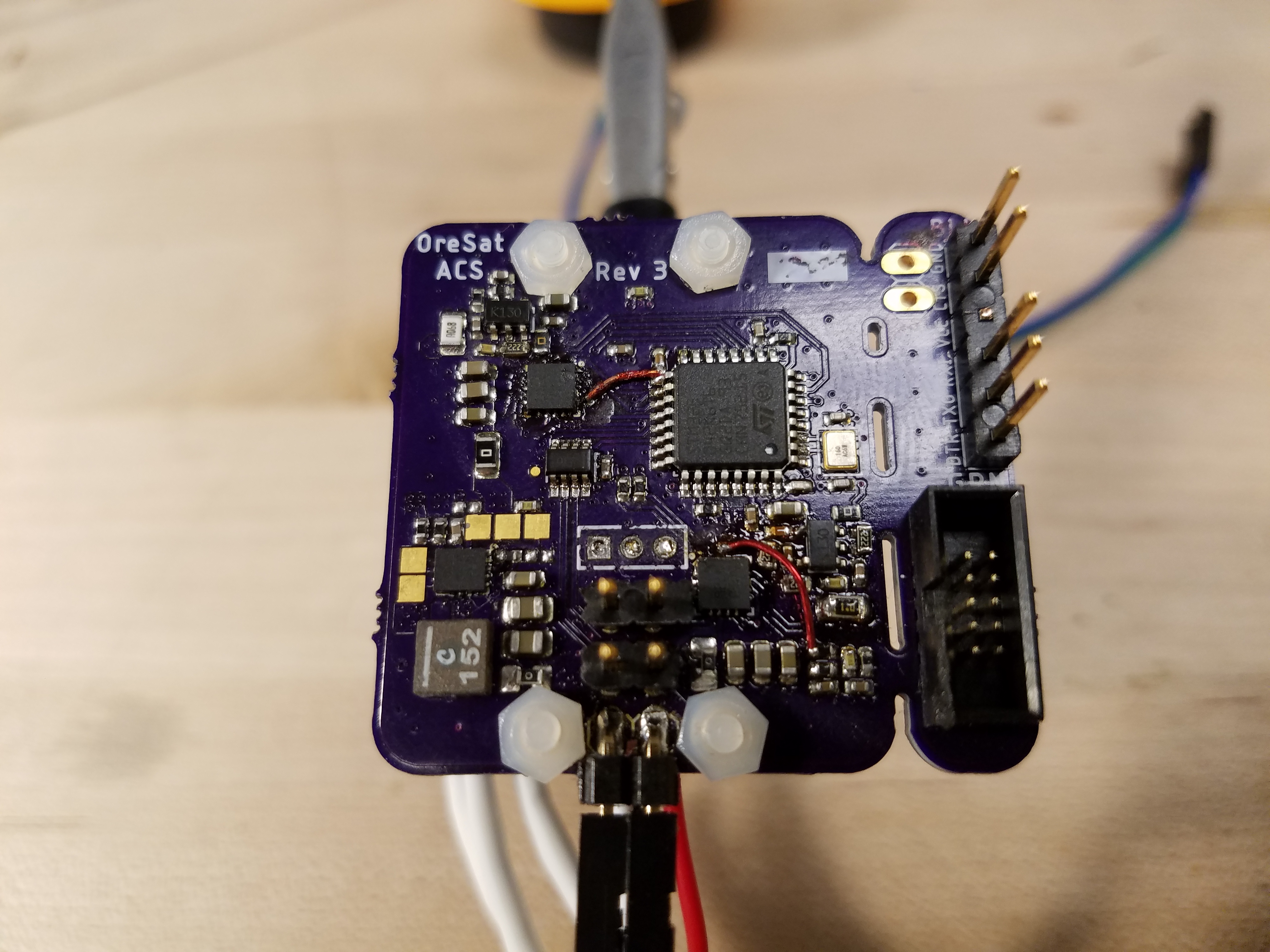
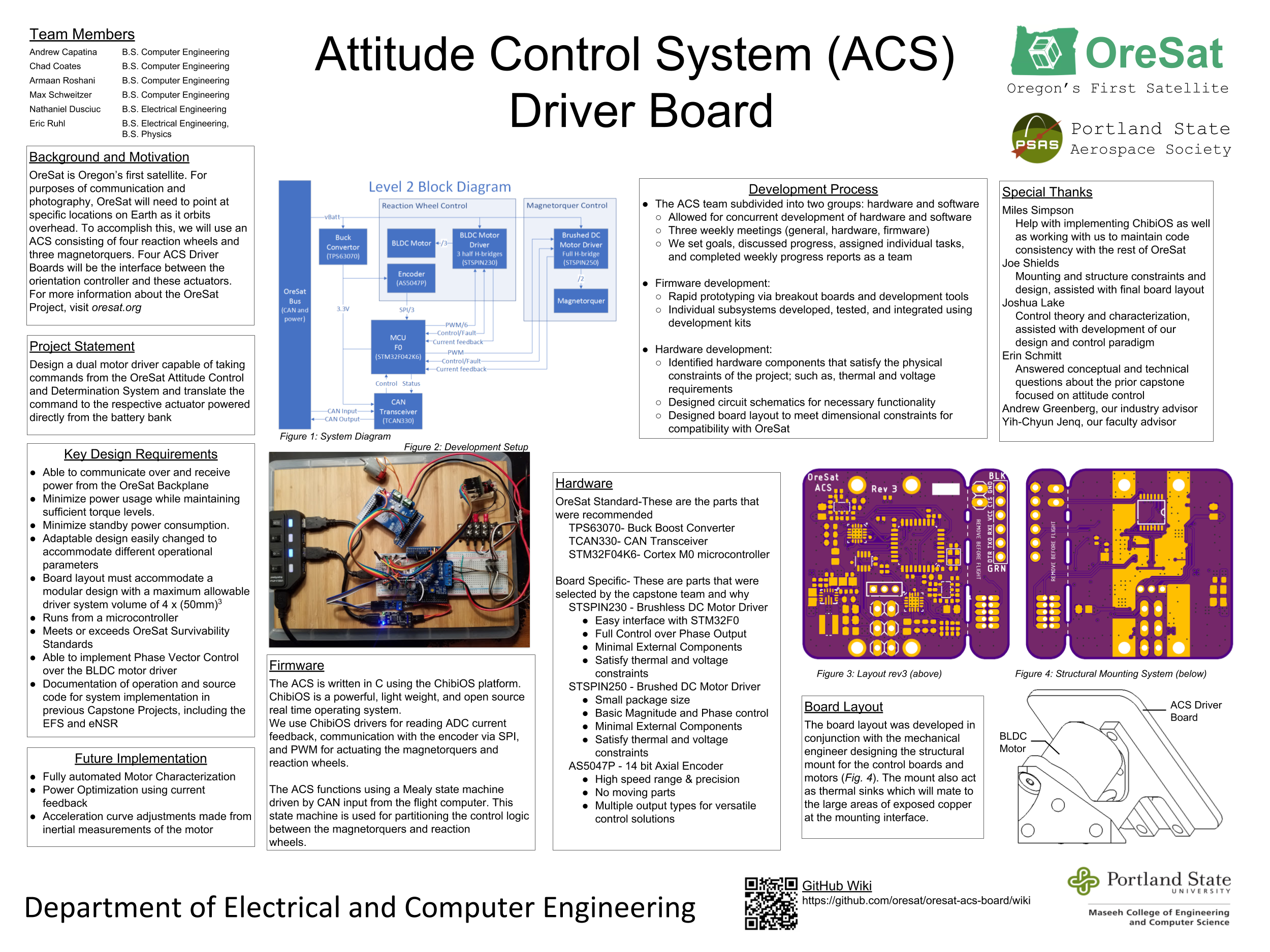
The attitude control system (ACS) inside oresat needs to orientate the position of the cubesat in space. This will be acheived in two ways; With brushless DC motors (BLDC) and with Magnetorquers. We are designing a PCB that controls both systems.
Find the project design contraints at, https://github.com/oresat/oresat-acs-board/blob/master/Project%20Design%20Constraints.md "Project Design Constraints"
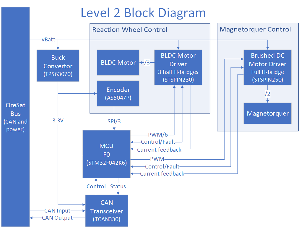
ACS Level 2 Block Diagram Version 3.2
System Hardware Overview
Deatailed Hardware Reference Guide
EagleCAD Files:
Link to the EagleCAD schematics and board layouts
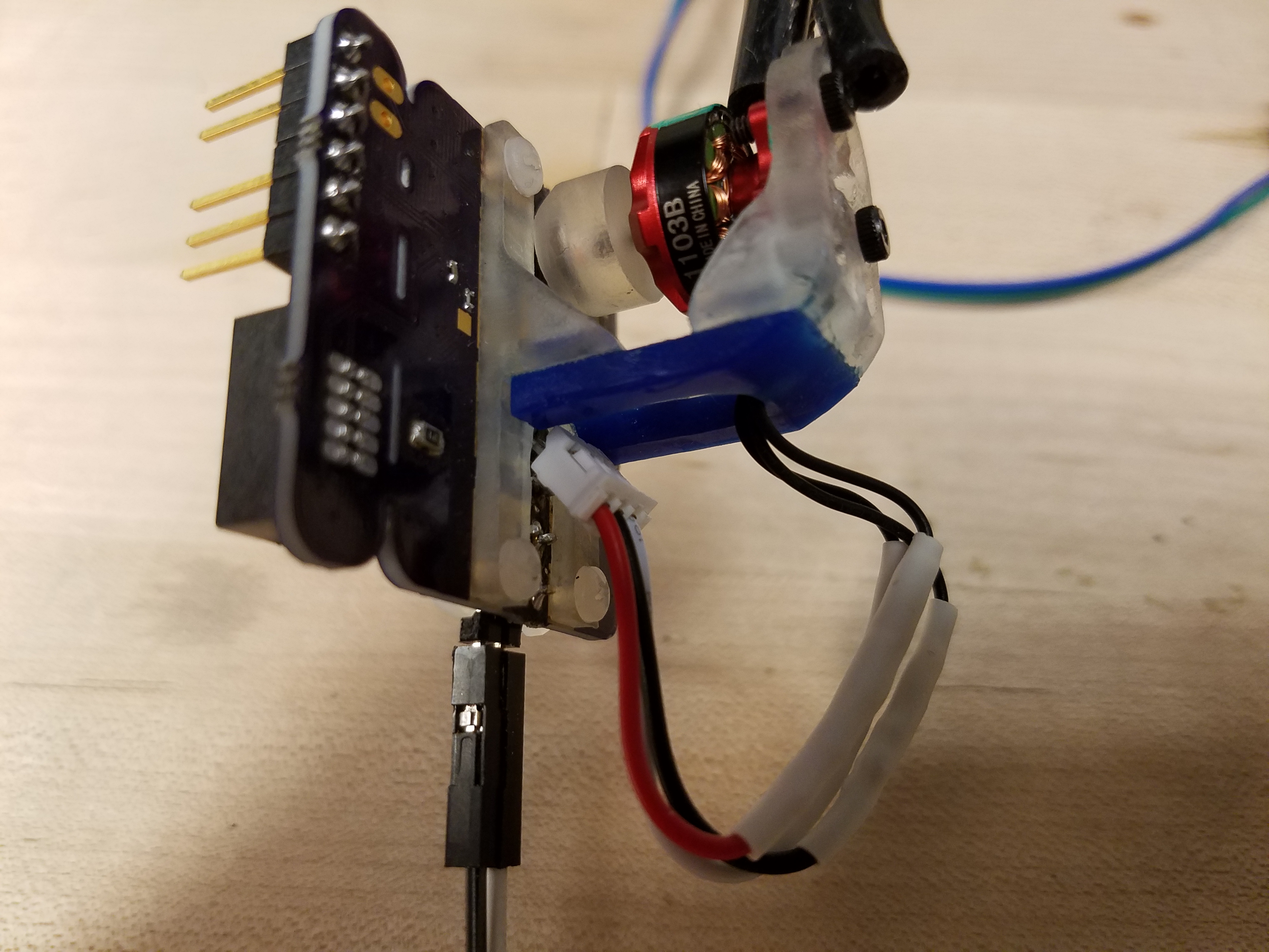
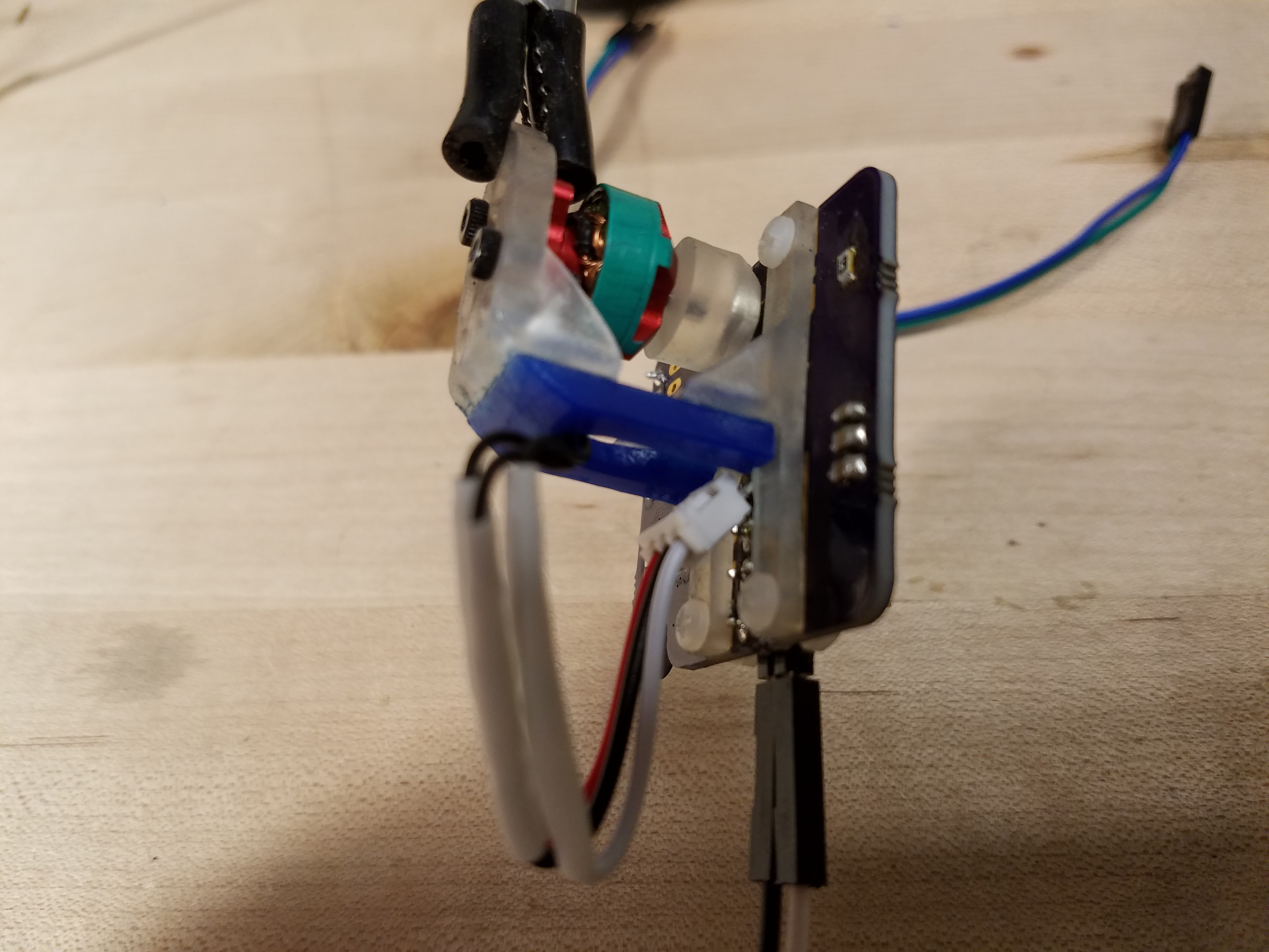
Manufacturing Photos:
Manufacturing photos of board layouts and CAD model of mounting strategy
Capstone Poster:
Link to Capstone poster in Google Drive
System Firmware:
Check here for the firmware information
Research and Tutorials / Ramp Up Documents:
Brushless DC (BLDC) motor control is a challenging form of motor control. We found numerous helpful tutorials and references. https://github.com/oresat/oresat-acs-board/blob/master/Ramp%20Up.md "Link to research references and bibliography, start here for a ramp up on ACS"
Final Product: