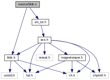
#include "bldc.h"
#include "sin_lut.h"
Go to the source code of this file.
|
| bldc * | motor |
| |
| static const ADCConversionGroup | adcgrpcfg |
| | ADC conversion group, used to configure the ADC driver Mode: Continuous, 1 sample of 1 channel, SW triggered. Channels: A0 Slowest sample rate possible, as putting it too high can lock other systems out. More...
|
| |
| static PWMConfig | pwmRWcfg |
| | Pwm driver configuration structure. More...
|
| |
◆ adcerrorcallback()
| static void adcerrorcallback |
( |
ADCDriver * |
adcp, |
|
|
adcerror_t |
err |
|
) |
| |
|
static |
◆ bldcExit()
| void bldcExit |
( |
bldc * |
pbldc | ) |
|
Function prototype with no return type. Takes bldc type as paramater.
@ brief Tear down drivers in a sane way.
259 adcStopConversion(&ADCD1);
int started
Definition: bldc.h:113
void bldcStop(bldc *pbldc)
Stops BLDC control.
Definition: bldc.c:227
thread_t * p_spi_thread
Definition: bldc.h:111
bldc * motor
Definition: bldc.c:4
◆ bldcInit()
| void bldcInit |
( |
bldc * |
pbldc | ) |
|
Sets up initial values for the BLDC object.
Function prototype with no return type. Takes bldc type as paramater.
194 adcStart(&ADCD1, NULL);
199 sizeof(wa_spiThread),
adcsample_t samples[ADC_GRP_NUM_CHANNELS *ADC_GRP_BUF_DEPTH]
Definition: bldc.h:112
#define SKIP
Definition: bldc.h:42
sinctrl_t v
Definition: bldc.h:100
int started
Definition: bldc.h:113
uint16_t count
Definition: bldc.h:95
uint16_t scale
period counter
Definition: bldc.h:95
sinctrl_t const * sinctrl
Definition: bldc.h:109
uint8_t stretch_count
Definition: bldc.h:105
#define STRETCH
Definition: bldc.h:41
sinctrl_t w
Definition: bldc.h:100
uint16_t position
Definition: bldc.h:107
sinctrl_t phase_shift
signals
Definition: bldc.h:100
const sinctrl_t sinctrl360[360]
Definition: sin_lut.h:6
uint16_t steps
scales the duty cycle
Definition: bldc.h:95
thread_t * p_spi_thread
Definition: bldc.h:111
#define SCALE
Definition: bldc.h:39
uint16_t stretch
number of steps in lut
Definition: bldc.h:95
#define STEPS
Definition: bldc.h:40
sinctrl_t u
Definition: bldc.h:100
bldc * motor
Definition: bldc.c:4
uint16_t skip
Definition: bldc.h:95
static const ADCConversionGroup adcgrpcfg
ADC conversion group, used to configure the ADC driver Mode: Continuous, 1 sample of 1 channel...
Definition: bldc.c:24
bool openLoop
Definition: bldc.h:108
#define ADC_GRP_BUF_DEPTH
Definition: bldc.h:62
◆ bldcSetDC()
| void bldcSetDC |
( |
uint8_t |
channel, |
|
|
uint16_t |
dc |
|
) |
| |
Changes duty cycle for a given channel.
Function prototype with no return type. Takes 8 bit unsigned integer and a 16 bit unsigned integer as argument.
247 PWM_PERCENTAGE_TO_WIDTH(&PWMD1,
scale(dc))
static sinctrl_t scale(sinctrl_t duty_cycle)
Scales the duty ccycle value from LUT 0 - 100%.
Definition: bldc.c:83
◆ bldcStart()
| void bldcStart |
( |
bldc * |
pbldc | ) |
|
Enables the three PWM channels, starting to go through the LUT.
Function prototype with no return type. Takes bldc type as paramater.
215 pwmEnablePeriodicNotification(&PWMD1);
217 pwmEnableChannel(&PWMD1,
PWM_U,PWM_PERCENTAGE_TO_WIDTH(&PWMD1,
motor->
u));
218 pwmEnableChannel(&PWMD1,
PWM_V,PWM_PERCENTAGE_TO_WIDTH(&PWMD1,
motor->
v));
219 pwmEnableChannel(&PWMD1,
PWM_W,PWM_PERCENTAGE_TO_WIDTH(&PWMD1,
motor->
w));
sinctrl_t v
Definition: bldc.h:100
static PWMConfig pwmRWcfg
Pwm driver configuration structure.
Definition: bldc.c:158
int started
Definition: bldc.h:113
#define PWM_U
PWM signals.
Definition: bldc.h:57
sinctrl_t w
Definition: bldc.h:100
#define PWM_V
Definition: bldc.h:58
sinctrl_t u
Definition: bldc.h:100
bldc * motor
Definition: bldc.c:4
#define PWM_W
Definition: bldc.h:59
◆ bldcStop()
| void bldcStop |
( |
bldc * |
pbldc | ) |
|
Stops BLDC control.
Function prototype with no return type. Takes bldc type as paramater.
231 pwmDisableChannel(&PWMD1,
PWM_U);
232 pwmDisableChannel(&PWMD1,
PWM_V);
233 pwmDisableChannel(&PWMD1,
PWM_W);
234 pwmDisablePeriodicNotification(&PWMD1);
int started
Definition: bldc.h:113
#define PWM_U
PWM signals.
Definition: bldc.h:57
#define PWM_V
Definition: bldc.h:58
#define PWM_W
Definition: bldc.h:59
◆ encoderToLut()
| static uint16_t encoderToLut |
( |
uint16_t |
position | ) |
|
|
static |
Translates encoder position into a useable LUT value.
Since it takes 6 passes through the LUT to get one physical revolution of the motor, we need a way to index a value of 0 - 2^14 into a value of 0 - 360, in 6 separate ranges
static const uint16_t chunk_low[6]
The low value used to break up the encoder value into regions.
Definition: bldc.h:123
#define CHUNK_SIZE
chunk size is the number
Definition: bldc.h:50
#define ENCODER_MAX
encoder has 14 bits of precision
Definition: bldc.h:45
#define STEPS
Definition: bldc.h:40
#define CHUNK_AMOUNT
Definition: bldc.h:48
◆ pwmpcb()
| static void pwmpcb |
( |
PWMDriver * |
pwmp | ) |
|
|
static |
Periodic callback of the PWM driver.
At the end of each period, we call this, and go to the next step in the LUT, which changes absed off of closed or open loop control. Holds the logic for stretching, skipping, and repeating, to modify the LUT values on the fly.
If open loop, ignore encoder feedback.
Calculate the difference between the current step in the LUT and the next step in the LUT, and break it up into the desired amount of steps in between the two
uint16_t current_sin_u
should be by 120 degrees
Definition: bldc.h:102
uint16_t current_sin_v
Definition: bldc.h:102
sinctrl_t v
Definition: bldc.h:100
#define PWM_U
PWM signals.
Definition: bldc.h:57
uint16_t current_sin_w
Definition: bldc.h:102
uint16_t next_sin_w
Definition: bldc.h:102
uint16_t next_sin_v
Definition: bldc.h:102
sinctrl_t const * sinctrl
Definition: bldc.h:109
uint8_t stretch_count
Definition: bldc.h:105
void bldcSetDC(uint8_t channel, uint16_t dc)
Changes duty cycle for a given channel.
Definition: bldc.c:243
sinctrl_t w
Definition: bldc.h:100
uint16_t position
Definition: bldc.h:107
#define PWM_V
Definition: bldc.h:58
sinctrl_t phase_shift
signals
Definition: bldc.h:100
static uint16_t encoderToLut(uint16_t position)
Translates encoder position into a useable LUT value.
Definition: bldc.c:43
uint16_t stretch
number of steps in lut
Definition: bldc.h:95
sinctrl_t u
Definition: bldc.h:100
uint16_t next_sin_u
Definition: bldc.h:102
bldc * motor
Definition: bldc.c:4
uint16_t skip
Definition: bldc.h:95
#define PWM_W
Definition: bldc.h:59
uint8_t sin_diff
Definition: bldc.h:106
bool openLoop
Definition: bldc.h:108
◆ scale()
Scales the duty ccycle value from LUT 0 - 100%.
uint16_t scale
period counter
Definition: bldc.h:95
bldc * motor
Definition: bldc.c:4
◆ THD_FUNCTION()
| THD_FUNCTION |
( |
spiThread |
, |
|
|
arg |
|
|
) |
| |
Prototype for spi thread function.
58 chRegSetThreadName(
"spiThread");
61 spiAcquireBus(&SPID1);
63 while (!chThdShouldTerminateX()) {
67 while(SPID1.state != SPI_READY) {}
75 spiReleaseBus(&SPID1);
uint16_t spi_rxbuf[2]
Definition: bldc.h:110
uint16_t position
Definition: bldc.h:107
static const SPIConfig spicfg
Control structure used to configure the SPI driver.
Definition: bldc.h:142
bldc * motor
Definition: bldc.c:4
◆ THD_WORKING_AREA()
Handles the SPI transaction, getting the position from the encoder.
◆ adcgrpcfg
| const ADCConversionGroup adcgrpcfg |
|
static |
Initial value:= {
TRUE,
NULL,
ADC_CFGR1_CONT | ADC_CFGR1_RES_12BIT,
ADC_TR(0, 0),
ADC_SMPR_SMP_239P5,
ADC_CHSELR_CHSEL0
}
#define ADC_GRP_NUM_CHANNELS
Definition: bldc.h:61
static void adcerrorcallback(ADCDriver *adcp, adcerror_t err)
Currently not used.
Definition: bldc.c:11
ADC conversion group, used to configure the ADC driver Mode: Continuous, 1 sample of 1 channel, SW triggered. Channels: A0 Slowest sample rate possible, as putting it too high can lock other systems out.
- Todo:
- : combine this with a timer to not spam interrupts so much?
◆ motor
◆ pwmRWcfg
Initial value:= {
{
{PWM_OUTPUT_ACTIVE_HIGH|PWM_COMPLEMENTARY_OUTPUT_ACTIVE_HIGH, NULL},
{PWM_OUTPUT_ACTIVE_HIGH|PWM_COMPLEMENTARY_OUTPUT_ACTIVE_HIGH, NULL},
{PWM_OUTPUT_ACTIVE_HIGH|PWM_COMPLEMENTARY_OUTPUT_ACTIVE_HIGH, NULL},
{PWM_OUTPUT_DISABLED, NULL}
},
0,
0,
0
}
#define PWM_TIMER_FREQ
Definition: bldc.h:52
#define PWM_PERIOD
Definition: bldc.h:54
static void pwmpcb(PWMDriver *pwmp)
Periodic callback of the PWM driver.
Definition: bldc.c:96
Pwm driver configuration structure.
PWM_TIMER_FREQ is our timer clock in Hz
PWM_PERIOD period in ticks
Configured with pwmpcb as the periodic callback PWM channels 0,1,2 are all active high, with a complementary output and no channel callback