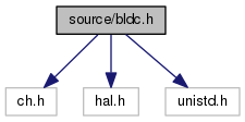
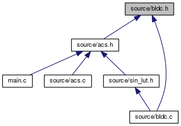
#include "ch.h"
#include "hal.h"
#include <unistd.h>
Go to the source code of this file.
|
| struct | bldc |
| | The structure that defines and characterizes a motor and how it's being control. More...
|
| |
|
| static const uint16_t | chunk_low [6] |
| | The low value used to break up the encoder value into regions. More...
|
| |
| static const SPIConfig | spicfg |
| | Control structure used to configure the SPI driver. More...
|
| |
◆ ADC_GRP_BUF_DEPTH
| #define ADC_GRP_BUF_DEPTH 8 |
◆ ADC_GRP_NUM_CHANNELS
| #define ADC_GRP_NUM_CHANNELS 1 |
◆ CHUNK_AMOUNT
chunk amount is the number of times through the LUT for 1 revolution of the reaction wheel
◆ CHUNK_SIZE
◆ DEBUG_CHP
◆ DEBUG_SERIAL
◆ ENCODER_MAX
| #define ENCODER_MAX 1<<14 |
encoder has 14 bits of precision
◆ OPENLOOP
- Todo:
- : openloop is going away
◆ PWM_FREQ
◆ PWM_PERIOD
◆ PWM_TIMER_FREQ
| #define PWM_TIMER_FREQ 48e6 |
◆ PWM_U
◆ PWM_V
◆ PWM_W
◆ SCALE
- Todo:
- : the definitions of STEP, STRETCH, and SKIP evolved over the course of various experiments. These will completely change in v2.0. Below is their intended and eventual meanings.
STEPS: the number of discrete steps in the LUT
STRETCH: How many periods the current LUT value is repeated
SKIP: How many steps are skipped in the LUT to get the next value
SMOOTH: Smoothing out the transition between LUT values by increasing the amount of steps in between
SCALE: Duty cycle scaling factor from 0-100 %
◆ sinctrl_t
| #define sinctrl_t uint16_t |
◆ SKIP
◆ STEPS
◆ STRETCH
◆ THREAD_SIZE
- Todo:
- : had to reduce this to compile with new ADC code We should figure out what an actual good value is
◆ bldcExit()
| void bldcExit |
( |
bldc * |
pbldc | ) |
|
Function prototype with no return type. Takes bldc type as paramater.
@ brief Tear down drivers in a sane way.
259 adcStopConversion(&ADCD1);
int started
Definition: bldc.h:113
void bldcStop(bldc *pbldc)
Stops BLDC control.
Definition: bldc.c:227
thread_t * p_spi_thread
Definition: bldc.h:111
bldc * motor
Definition: bldc.c:4
◆ bldcInit()
| void bldcInit |
( |
bldc * |
pbldc | ) |
|
Function prototype with no return type. Takes bldc type as paramater.
Function prototype with no return type. Takes bldc type as paramater.
194 adcStart(&ADCD1, NULL);
199 sizeof(wa_spiThread),
adcsample_t samples[ADC_GRP_NUM_CHANNELS *ADC_GRP_BUF_DEPTH]
Definition: bldc.h:112
#define SKIP
Definition: bldc.h:42
sinctrl_t v
Definition: bldc.h:100
int started
Definition: bldc.h:113
uint16_t count
Definition: bldc.h:95
uint16_t scale
period counter
Definition: bldc.h:95
sinctrl_t const * sinctrl
Definition: bldc.h:109
uint8_t stretch_count
Definition: bldc.h:105
#define STRETCH
Definition: bldc.h:41
sinctrl_t w
Definition: bldc.h:100
uint16_t position
Definition: bldc.h:107
sinctrl_t phase_shift
signals
Definition: bldc.h:100
const sinctrl_t sinctrl360[360]
Definition: sin_lut.h:6
uint16_t steps
scales the duty cycle
Definition: bldc.h:95
thread_t * p_spi_thread
Definition: bldc.h:111
#define SCALE
Definition: bldc.h:39
uint16_t stretch
number of steps in lut
Definition: bldc.h:95
#define STEPS
Definition: bldc.h:40
sinctrl_t u
Definition: bldc.h:100
bldc * motor
Definition: bldc.c:4
uint16_t skip
Definition: bldc.h:95
static const ADCConversionGroup adcgrpcfg
ADC conversion group, used to configure the ADC driver Mode: Continuous, 1 sample of 1 channel...
Definition: bldc.c:24
bool openLoop
Definition: bldc.h:108
#define ADC_GRP_BUF_DEPTH
Definition: bldc.h:62
◆ bldcSetDC()
| void bldcSetDC |
( |
uint8_t |
channel, |
|
|
uint16_t |
dc |
|
) |
| |
Changes duty cycle for a given channel.
Function prototype with no return type. Takes 8 bit unsigned integer and a 16 bit unsigned integer as argument.
247 PWM_PERCENTAGE_TO_WIDTH(&PWMD1,
scale(dc))
static sinctrl_t scale(sinctrl_t duty_cycle)
Scales the duty ccycle value from LUT 0 - 100%.
Definition: bldc.c:83
◆ bldcStart()
| void bldcStart |
( |
bldc * |
pbldc | ) |
|
Function prototype with no return type. Takes bldc type as paramater.
Function prototype with no return type. Takes bldc type as paramater.
215 pwmEnablePeriodicNotification(&PWMD1);
217 pwmEnableChannel(&PWMD1,
PWM_U,PWM_PERCENTAGE_TO_WIDTH(&PWMD1,
motor->
u));
218 pwmEnableChannel(&PWMD1,
PWM_V,PWM_PERCENTAGE_TO_WIDTH(&PWMD1,
motor->
v));
219 pwmEnableChannel(&PWMD1,
PWM_W,PWM_PERCENTAGE_TO_WIDTH(&PWMD1,
motor->
w));
sinctrl_t v
Definition: bldc.h:100
static PWMConfig pwmRWcfg
Pwm driver configuration structure.
Definition: bldc.c:158
int started
Definition: bldc.h:113
#define PWM_U
PWM signals.
Definition: bldc.h:57
sinctrl_t w
Definition: bldc.h:100
#define PWM_V
Definition: bldc.h:58
sinctrl_t u
Definition: bldc.h:100
bldc * motor
Definition: bldc.c:4
#define PWM_W
Definition: bldc.h:59
◆ bldcStop()
| void bldcStop |
( |
bldc * |
pbldc | ) |
|
Function prototype with no return type. Takes bldc type as paramater.
Function prototype with no return type. Takes bldc type as paramater.
231 pwmDisableChannel(&PWMD1,
PWM_U);
232 pwmDisableChannel(&PWMD1,
PWM_V);
233 pwmDisableChannel(&PWMD1,
PWM_W);
234 pwmDisablePeriodicNotification(&PWMD1);
int started
Definition: bldc.h:113
#define PWM_U
PWM signals.
Definition: bldc.h:57
#define PWM_V
Definition: bldc.h:58
#define PWM_W
Definition: bldc.h:59
◆ THD_FUNCTION()
| THD_FUNCTION |
( |
spiThread |
, |
|
|
arg |
|
|
) |
| |
Prototype for spi thread function.
58 chRegSetThreadName(
"spiThread");
61 spiAcquireBus(&SPID1);
63 while (!chThdShouldTerminateX()) {
67 while(SPID1.state != SPI_READY) {}
75 spiReleaseBus(&SPID1);
uint16_t spi_rxbuf[2]
Definition: bldc.h:110
uint16_t position
Definition: bldc.h:107
static const SPIConfig spicfg
Control structure used to configure the SPI driver.
Definition: bldc.h:142
bldc * motor
Definition: bldc.c:4
◆ THD_WORKING_AREA()
◆ chunk_low
| const uint16_t chunk_low[6] |
|
static |
Initial value:= {
5 * CHUNK_SIZE
}
#define CHUNK_SIZE
chunk size is the number
Definition: bldc.h:50
The low value used to break up the encoder value into regions.
Allows us to translate the encoder 0 - 2^14 into 6 discrete chunks of 0-360 for use in the LUT.
◆ spicfg
Initial value:= {
false,
NULL,
GPIOA,
GPIOA_SPI1_NSS,
SPI_CR1_BR_0|SPI_CR1_BR_1|SPI_CR1_BR_2|SPI_CR1_CPHA,
SPI_CR2_DS_0|SPI_CR2_DS_1|SPI_CR2_DS_2|SPI_CR2_DS_3,
}
Control structure used to configure the SPI driver.
GPIOA_SPI1_NSS is the pin used to initially select the SPI slave. The mask for SPI Control Register 1 sets the frequency of data transfers and sets the clock polarity. The mask for SPI control Register 2 sets the size of the transfer buffer, 16 bits.